SSB
An excerpt from Advanced Marine Electrics and Electronics Troubleshooting: A Manual for Boatowners and Marine Technicians

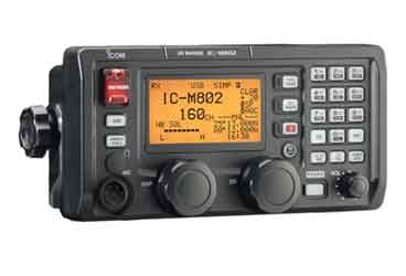
Single-sideband (SSB) radio is the long-range counterpart to VHF radio. Where marine VHF is limited to line-of-sight communications and a maximum of about 25 miles, SSB radio has the potential to transmit and receive over hundreds or even thousands of miles. An SSB radio bounces radio signals off the lower layers of the earth’s atmosphere, which in turn reflect the signals back to earth. (You can think of SSB transmissions as giant triangles spanning many miles.)
Voltage and Current Requirements
An SSB’s appetite for amps covers a fairly broad spectrum, ranging from about 2 to 3 amps in Standby/Receive mode to about 30 amps when transmitting. This is not too much of a problem unless the operator is the chatty type or spends a lot of time downloading weather charts via a modem. However, 30 amps of consumption is a considerable amount, and it will drain batteries rather rapidly if they are not being recharged.
Installation guidelines
• Be sure to use correctly sized power feed wires to serve the unit, especially in consideration of restricting voltage drop to a maximum of 3%. Based on ABYC E-11, you will need a minimum of 6 AWG (13 mm2) wire to supply power to a 12V SSB set over a 20-foot cable run.
• Adhere to voltage supply parameters. Most if not all SSB units operate at a nominal 12V. For a boat with a 24V or 32V system, you will need a DC-to-DC power converter. Overvoltage supply to the transceiver will damage the unit quicker than you can snap your fingers! A typical l2V (nominal) SSB has a voltage operating range of 13.6VDC, ±15% maximum. Consider this 15% an absolute maximum because performance will definitely be affected if power falls below -15%.
• Use the 3% voltage drop parameter to ensure peak performance. Lower-than acceptable voltage will have a profound impact on power output from the unit and its potential range. It may be useful to think of potential power out of the unit as proportional to the power available to operate the unit.
• An SSB requires a first-class grounding system to function at its peak, and the antenna needs what is known as a counterpoise, a ground that is an integral part of the antenna system.
• For best results, use the multicable harness provided by the SSB manufacturer, which typically includes the coaxial antenna lead, power cables, and a cable to connect the automatic antenna tuner (a commonly specified available option). All the individual cables in the harness are terminated with watertight connectors for the tuner or transceiver, and all the individual conductors within each cable are connected to the right pins. Stick with the original manufacturer’s harness! This is not an area where you will win high marks for creativity.
Regulations for SSB use vary from one country to another. In the United States, FCC rules apply. Additionally, specific regulations apply if the radio includes DSC and GMDSS.
This is where a true electronics equipment specialty house can put you on the right course. Electronics specialists are usually FCC licensed and will be well versed in the specific regulations as they apply not only to installation of equipment, but also to licensing requirements for equipment operators. Inquire before you get in trouble, because the rules changed a few years ago. In some cases, an FCC license is required to perform installations.
Noise Issues with SSB
Electrical “noise” on board can dramatically affect an SSB’s ability to produce clear, static-free signals in Receive mode. Potential noise emitters include anything that relies on an electrical spark for its operation-virtually any motor, fluorescent lights, and relays and solenoids. After installation, test your SSB to ensure that the antenna is not receiving any emitted noise. Since SSBs operate over a fairly broad frequency spectrum (from 2 MHz to 22 MHz), it is hard to predict which electrical devices might contribute to excessive background noise. To help you find the culprit, conduct a process-of-elimination test, as follows:
1 Set the radio between channels at the low end of the spectrum (towards the 2 MHz end).
2 Activate other AC and DC equipment one at a time.
3 Run all the engines, including AC generators.
4 Repeat this test sequence at all of the commonly used frequencies to be sure that you haven’t missed an annoying RFI emitter running at a higher frequency.
Keep in mind that some background noise is normal and unavoidable. But if, for example, audible noise dramatically increases when you turn on a fluorescent light, you’ve isolated a culprit. Also keep in mind that some electrical equipment is cyclical and may only function intermittently (such as bilge pumps). Check cycling loads when they’re actually operating, not just with their power activated.
If you identify a noise source during this elimination process, it’s best to consult the radio manufacturer or its local dealer to determine the best type and rating of filter to install. Your concerns, as the electrical installer, are largely limited to those mentioned: the power supply, cabling, noise, antenna, coaxial cable, and antenna counterpoise. Any problems not related to these issues must be addressed by an electronics technician.
Read more from Ed Sherman on his blog, Ed’s Boat Tips.