Everyone has a favorite piece of gear on their boat. Aboard our Hunter 44DS, Groovy, my husband, Mark, and I certainly have a fond spot for our radar-integrated chart plotter. But we both agree there’s nothing we love more than our watermaker. Before our nearly four-year cruise of Mexico’s Pacific coast and Sea of Cortez, Mark installed a high-capacity, engine-driven EchoTec 900-BML-2 watermaker, manufactured in Trinidad, that is officially rated to produce 38 gallons per hour. Cruising where water temperatures topped 75 degrees, our watermaker consistently produced a whopping 60 gallons per hour. How pure was it? Fresh water is rated by “total dissolved solids” (TDS), and drinking water is generally 500 ppm (parts per million) or less. We measured San Diego’s tap water at 350 ppm and commercially bottled water at 6 ppm. In the tropics the agua from our watermaker was between 75 and 95 ppm.
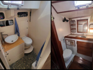
Unlike many Mexico cruisers who moor primarily at beautiful (but pricey) marinas, we lived exclusively at anchor, relying entirely on our watermaker for all of our water needs. We never filled the tanks from water on shore. But because we could top off our 140-gallon tanks in just over two hours, we enjoyed long showers, washed the salt and dirt off the deck and cockpit frequently, rinsed our snorkeling gear after every foray, and washed the inflatable kayak and dinghy regularly.
Why install a high-capacity watermaker? Simply put, we have never met a full-time, off-the-grid cruiser who complained that their watermaker was too big. Here’s the thinking that went into the purchase and installation of our unit.
Watermakers require a lot of power to run, and since all of our electricity was going to come from solar power and the engine’s alternator, a DC watermaker could not efficiently produce as large a volume of water as we wanted. We also didn’t want to listen to the noise of a watermaker running for hours on end. A generator could have powered a high-capacity AC watermaker, but we opted for an engine-driven system instead.
A watermaker involves many different components. Before we started, I made a cardboard mock-up of the high-pressure water pump, the heart of the system, which would ultimately hang below the engine and force the seawater through a series of filters and desalination membranes. So, prior to purchasing the watermaker, this mock-up gave us the confidence that the pump would fit into the engine compartment.
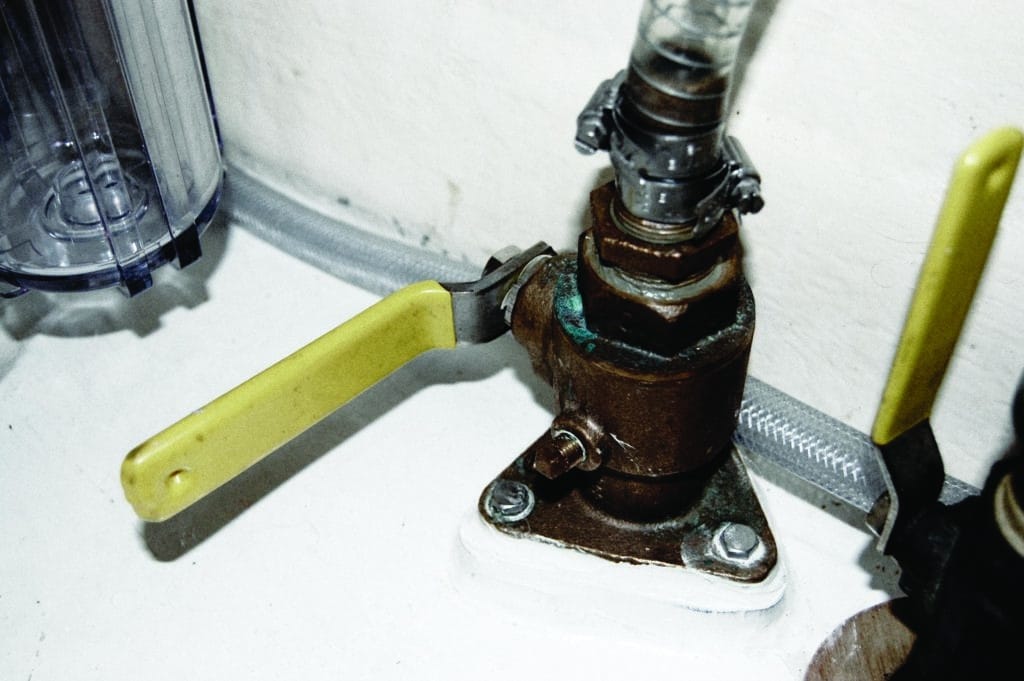
There are two dedicated through-hulls, one at each end of a watermaker. The saltwater intake through-hull is located below the waterline and draws raw ocean water into the system. At the opposite end, a brine water discharge through-hull located above the waterline flushes the salty reject water out of the boat.
Between these two through-hulls lies the actual watermaker, a series of filtration systems that remove increasingly tiny particles from the water. A high-pressure water pump drives this system, pushing seawater all the way through. The first sea strainer and “pre-filters” remove large particles. The last filtration stage is two 4-foot-long desalination membranes that remove microscopic sodium chloride (salt) particles prior to diverting the fully filtered fresh water to the boat’s tanks. Since our water pump was to be installed below the waterline, our watermaker came with an additional boost pump.
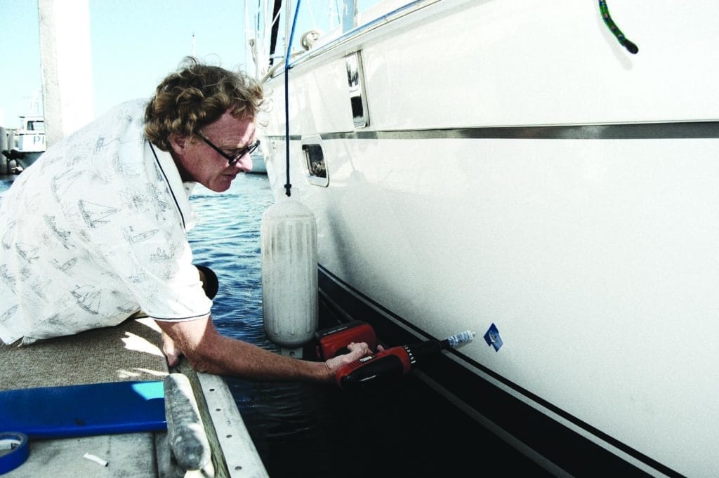
During a haulout, the top-notch Baja Naval boatyard in Ensenada, Mexico (just 70 miles south of San Diego), installed the dedicated saltwater intake through-hull. At the dock, Mark installed the brine discharge water through-hull on the side of the hull above the bootstripe. After five measurements, as he drilled that hole into our sparkling, new-to-us boat, we both held our breath. But we shouldn’t have worried; he got it just right.
The day our system arrived from Trinidad in a huge wooden crate — with the high-pressure water pump and desalination membranes screwed to the inside of the box for security during transport — was a bit overwhelming. Because each installation is unique, it is impossible for watermaker vendors to anticipate exactly which fittings will be required. Throughout our installation, we purchased the additional parts we needed locally.
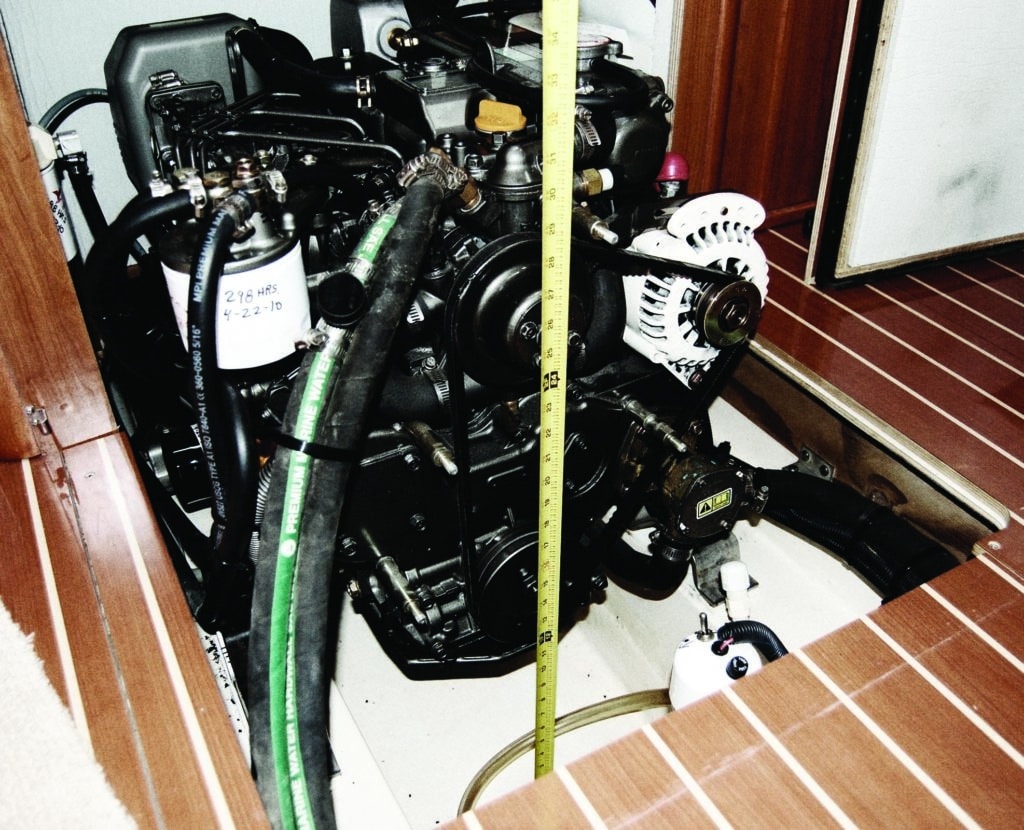
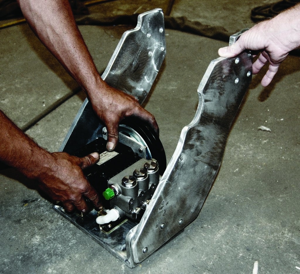
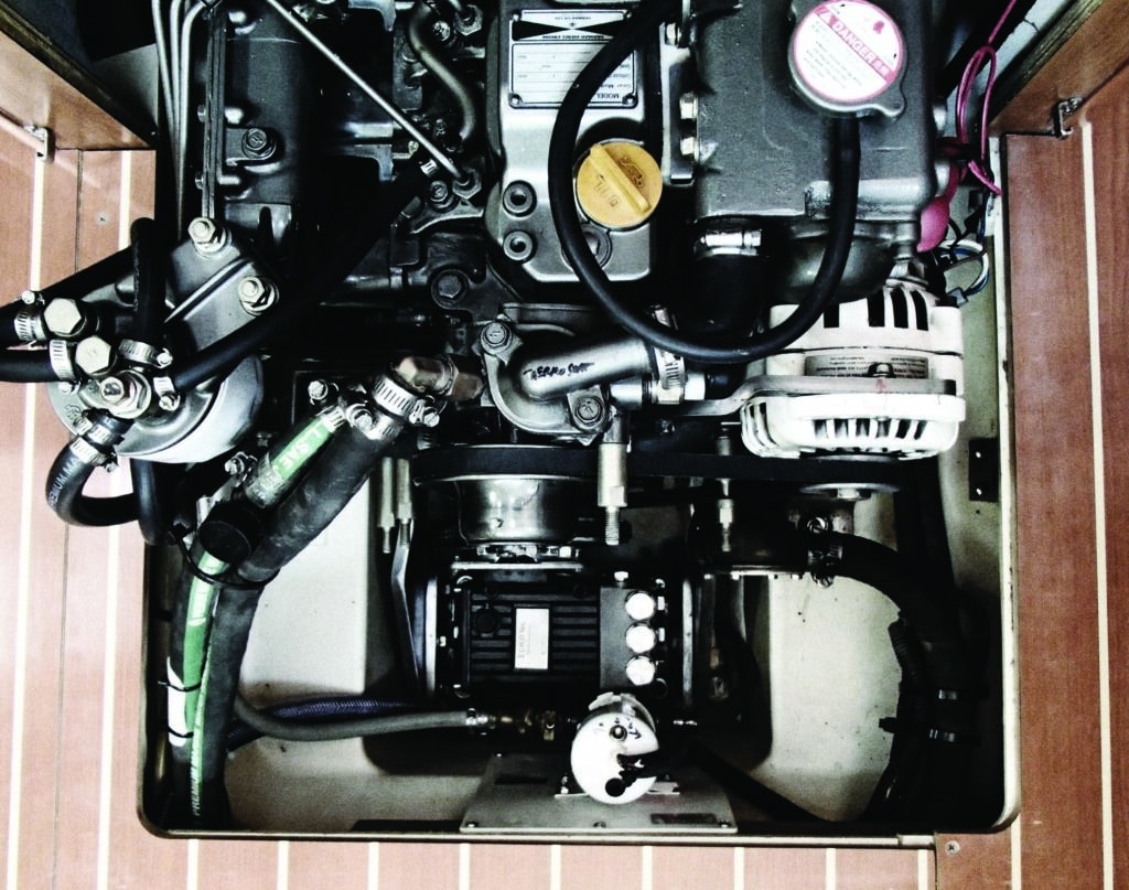
The driving force of our watermaker is the high-pressure water pump that is suspended off our Yanmar 4JH4E 54 hp engine. This pump is mounted onto the engine itself, rather than to the bulkheads or floorboards, because it needs to move with the engine. It’s operated by a 7-inch Yanmar PTO (power takeoff) pulley that’s bolted onto the crankshaft pulley. Together, they create a combined two-track pulley.
We turned to Ensenada’s brilliant metal fabricator Alejandro Ulloa to design a U-shaped shelf system to support the high-pressure water pump. Because steel would rust and stainless is too brittle, he used half-inch aluminum. Alejandro designed this bracket to ensure full adjustability for the pulley belt tension. The bracket consists of a shelf to support the pump and two vertical arms on either side of the shelf that attach to the engine’s motor mounts. Slotted holes in the shelf allow the water pump to slide fore and aft. Slotted holes where the shelf attaches to the arms allow the shelf to move up and down.
Once the bracket system was completed, Mark hung it from the engine’s motor mounts. Placing a scissors jack under the engine to support it while he removed the original motor-mount bolts, he inserted each of the two vertical arms of the water pump bracket in line with the motor mounts’ L-bracket holes on the side walls of the engine compartment. Then he installed new, longer motor-mount bolts of the same pitch and thread to accommodate the half-inch width of the aluminum bracket arms.
We both gasped when he finally got the bracket into position. It fit like a glove in the engine compartment with just a quarter-inch to spare on each side.
The engine now sat slightly differently on its motor mounts than before, with the bow end slightly elevated. This caused misalignment in the drive shaft and crankshaft flanges by a few thousandths of an inch. Mark adjusted the motor-mount heights to realign the engine to the prop shaft, using a feeler gauge to ensure that the gap between the top and bottom of the flanges was identical.
The next step was to determine which parts of the system would be above or below the waterline, because all the hose connections below the waterline would require two hose clamps. The easiest way to determine the waterline, scary as it sounds, is to attach a 5- to 10-foot translucent water hose to the saltwater intake through-hull and hold the end of the hose high overhead, then open the through-hull valve. I gasped as the water rose steadily in the hose, but it stopped about halfway up our galley counters. I hadn’t realized so much of our cabin was below the waterline!
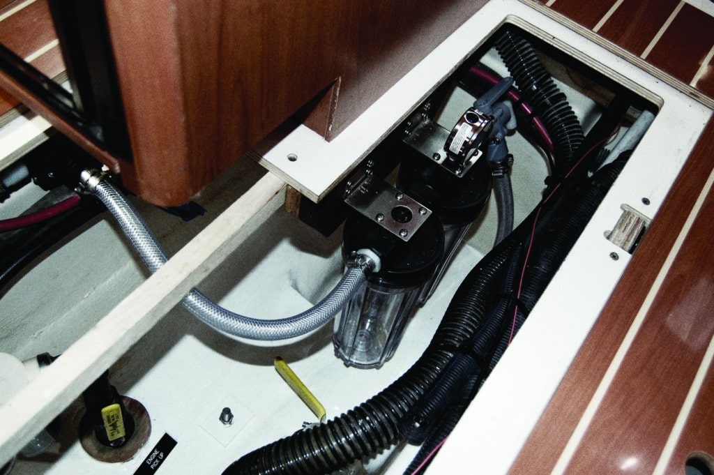
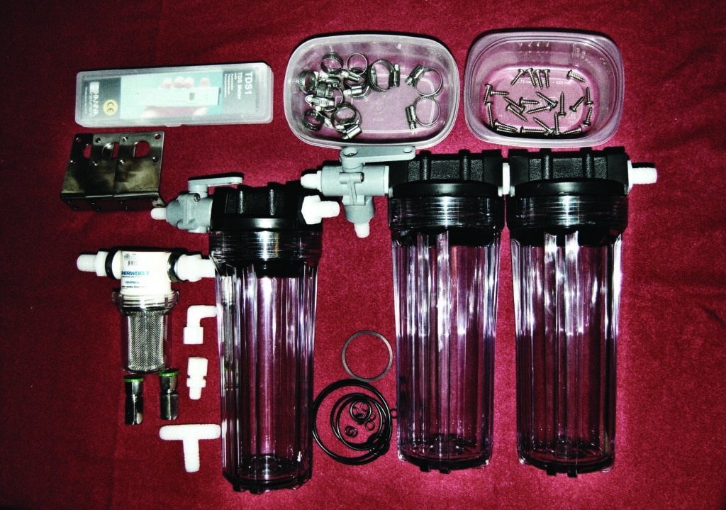
After the ocean water flows through the intake through-hull, it passes first through a sea strainer, which removes grasses and sea creatures, and then through two pre-filters. This pair of filters came pre-assembled in tandem from the factory. The first is a 20-micron pleated filter and the second is a 5-micron pleated filter, to remove successively smaller debris from the water on its way to the desalination membranes.
A third, charcoal filter would be used for “back-flushing” the system; that is, running fresh water from the holding tanks backward through the desalination membranes to clean them. This filter’s purpose is to remove any chlorine that might be lurking in the holding tanks from when they were previously filled from a water source on shore, because desalination membranes are quickly destroyed by chlorine.
Because the high-pressure pump would be located below the waterline, our installation required a boost pump to assist it. Mark mounted the sea strainer, the two pre-filters, the back-flush filter and the boost pump under the floorboards in the bilge compartment that contained the saltwater intake through-hull.
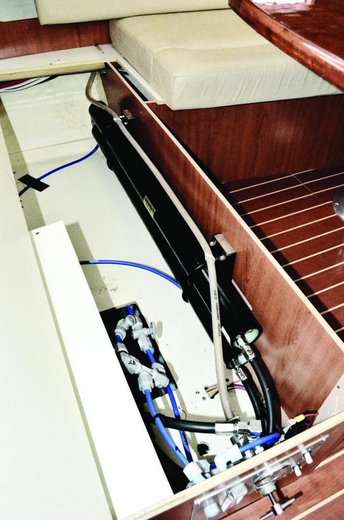
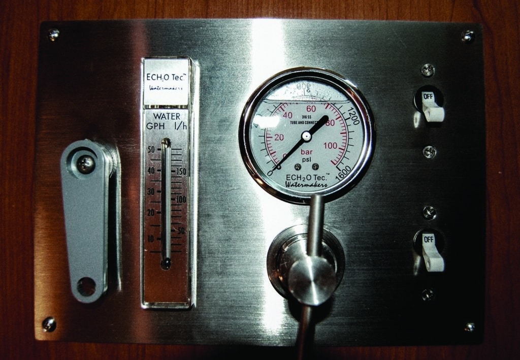
The pair of 4-foot desalination membranes was pre-connected at the factory by high-pressure metal fittings; Mark mounted them on the inner wall of a large locker under a settee. He placed the control panel on an adjacent outer wall of this locker. All of this was also below the waterline.
Now all the major components were in place — the high-pressure water pump, boost pump, sea strainer, three water filters, two membranes, control panel and two dedicated through-hulls — and it was time to connect them all with hoses. Mark brought the high-pressure hydraulic hose for the water pump to a heavy-equipment supplier to be cut to the correct length, because the stainless-steel mesh inside would have frayed with the cutting tools we had on hand. This company also installed the high-pressure hose fitting on the end of the hose so it could connect to the control panel. Mark used a PVC pipe cutter to custom-fit the CTS water lines and connected the lines with Sea Tech fittings, installing valves under the settee to control the flow of water to two of our three water tanks (more on that in a moment).
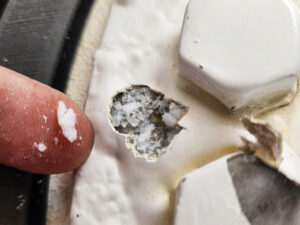
Connecting the CTS water lines to the freshwater holding tanks was a surprising challenge. The tanks did not have existing fittings for these lines (the tanks are made of low-density polyethylene plastic to which, theoretically, no adhesive can bond). On the top of one tank, Mark drilled and tapped a hole and screwed in a PVC plumbing compression fitting. To tighten the flange nut inside that tank, he temporarily removed the existing water-level sensor to squeeze his hand inside. Removing the sensor on the other tank would have required removing the flooring that was jigsaw-puzzled into the bulkheads. So for that tank he drilled and tapped a hole for a Sea Tech fitting that didn’t require tightening from inside the tank.
Prior to drilling the holes, Mark roughed the smooth tank surfaces with an emery cloth. He smeared a thick dollop of two-part Loctite Plastics Bonder onto the threads of both the holes and the fittings before installing them, and he slathered it around the fittings
afterward. The label of this product says, “Works on all plastics … including polyethylene.” Indeed, both fittings have worked flawlessly.
The watermaker control panel was built to accommodate a “sample tube” connection, and Mark attached a long, clear tube that could reach our galley sink. To turn on the system, he flips two switches, one for the boost pump and one for the clutch on the engine that activates the high-pressure water pump. Then he slowly raises the PSI pressure dial on the control panel to 800 psi, the optimal pressure for pushing seawater through the desalination membranes. Water initially flows through the sample tube and into our galley sink.
He runs the system for five minutes to flush five gallons of water through it before switching from the sample tube to the first water tank. It was too complicated to plumb the third tank under the distant V-berth into the system, so he fills that tank by attaching a hose to the sample tube and running it through a hatch to the bow tank’s deck-fill.
We wash the decks by filling 2.5-gallon water jugs from the sample tube, or we use the “sample hose through the hatch” technique. For drinking water, we fill 10 one-gallon bottles and add a few drops of trace minerals to each jug to replace the minerals removed by desalination.
We make water underway by slowing the boat from our 2,500 rpm cruising speed to 2,100 rpm, and we make water at anchor while idling at 1,500 rpm. An hour or two of water making finishes the job. After a particularly grueling passage, when the boat is covered in salt spray, we make water on our final approach, washing the decks and reveling in a long, hot shower. Totally refreshed when we arrive, we find the first views of our new anchorage especially inviting when seen over drinks from a sparkling clean cockpit.
Emily and Mark Fagan are currently enjoying a “land cruise” of North America in an RV. Their sailing adventures (and plentiful cruising tips) are chronicled on their blog. For more on EchoTec Watermakers, visit the company’s website (www.echotecwatermakers.com).
This article first appeared in the February 2015 issue of Cruising World.