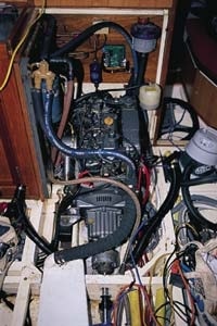
CW_0302_DN01.jpg
Last month, we outlined the criteria for selecting a replacement for your old engine. We follow that with some of the American Boat & Yacht Council (ABYC) recommendations and other details to keep in mind when installing it.
To get the best results from a repower, the first rule is to follow guidelines set by the manufacturer of the new engine. Also, to ensure a favorable survey and the good graces of your insurance company, the installation should comply with the ABYCs Standards and Technical Information Reports for Small Craft (ABYC, 410-956-1050, www. abyc.org). This may involve additional expense, but what you gain in safety, reliability, and peace of mind will be worth the investment.
Some necessary upgrades may be difficult or impossible to effect with the boat in the water, especially if a new and more powerful engine demands increases in the sizes of propeller and shaft.
Access: Try to provide a clear path to all of the engines service points, and also leave enough vertical clearance above the engine to remove the cylinder head. To allow better access, secondary fuel filters and other components can be detached from some engines and mounted in alternative locations. At the very least, clean the area around your engine beds, and paint it white to provide light and to better show engine leaks. A remote pump for the oil pan will make oil changes easier at sea. If you dont have an oil drip tray underneath the engine, install one: Federal law requires it.
Fuel system: Make a thorough inspection, from tank to lift pump, of all fuel lines and connections (see “Tanks for the Memories,” October 2000; “The Sensible Fuel System,” July 2001; and “Making the Grade,” November 2002). Many modern engines require larger-diameter fuel-delivery and fuel-return lines, which may in turn incur bigger fittings at the tank; a mistake commonly made in repowering procedures is retaining fuel lines that are too small. You also may have to replace your lift pump to meet the new fuel demands.
Acceptable fuel hoses meet specifications set by both the ABYC and the U.S. Coast Guard, and the designations are stamped on the line. Dont use anything less than U.S. Coast Guard Type A1 or Society of American Engineers (SAE) J 1527, and secure hoses against chafe. Metal tubing should be seamless copper or cupronickel with a minimum wall thickness of .027 inches. Joints in lines need to be airtight. Keep the number of joints to a minimum, and use permanently swaged hose end fittings or proper barbed end fittings and all-stainless-steel hose clamps; simply clamping hose over metal tubing will invite trouble. To make the final connection to the engine, use hose; vibration will work-harden copper tubing and make it brittle.
A good 30-micron primary fuel filter/water separator is essential. Better yet is a twin-filter system, with a vacuum gauge and two-way valve, which allows filter changes on the fly. If your fuel tank has a screen at the fuel pickup tube, get rid of it. This will be the first thing to get clogged, and youll have no quick remedy.
Cooling system: New engines have closed freshwater cooling systems. These in turn are cooled by raw water and may require a greater volume than did your old engine. An inadequate supply of raw water can lead to overheating, so to be on the safe side, if you find you need a bigger inside diameter on the cooling hose for the raw-water pump, you should upsize all components in the system. For example, some ball valves at through-hulls have a smaller inside diameter than adjacent piping and can cut flow by as much as two-thirds. Between the seacock and water pump, use reinforced marine-grade hose that wont collapse. Protect the hose against chafe, and double up stainless-steel hose clamps. Get rid of fine screens outside the hull that can clog (a bronze grate is fine); its sufficient to install a good seawater strainer (if its bronze and stainless steel, protect it against galvanic corrosion). Youll likely need an anti-siphon valve before cooling water enters the exhaust mixing elbow (see “Help Your Engine Keep Its Cool,” February 2002, for more cooling-system details).
Exhaust system: Any increase in horsepower will probably require a larger exhaust-hose diameter, which, in turn, will require upsizing all components, including the exhaust pipe through the hull. Closely follow the engine manufacturer’s recommendations regarding exhaust installation. For example, and this is particularly important for turbocharged engines, check back pressure with a manometer to see that it meets the manufacturer’s specs.
Some engine manufacturers offer a choice of exhaust elbows. If you have any parts fabricated, use compatible metals to prevent damage arising from galvanic corrosion.
A poorly designed and installed exhaust system is probably the most common repower flaw (see “Your Marine Exhaust System,” May 1998), and it has the potential to flood and ruin your engine. Typically, the installation requires a drop from the engines mixing elbow down to a waterlock, up to a loop at least 12 inches above the waterline, then out the exhaust pipe at the transom. Be sure to use only marine-grade exhaust hose, which is stamped SAE J 2006 or UL 1129.
Electrical system: The ABYC Standards explores electrical systems in detail. Deviating from these or the manufacturers guidelines can create a fire hazard or destroy expensive electrical equipment. Most new engines come prewired with plug-and-play instrument panel harnesses, but wiring to the batteries is the installers responsibility (see “A Smart Way to Bank Big Amps,” June 2002). Use only high-quality marine-grade wiring, and limit any voltage drop to less than 3 percent. The Standards, some installation manuals, and many electrical books provide tables for determining voltage drop and calculating appropriate wire sizes. Conservative sizing is particularly important for the starter cable. Overcurrent protection isnt required here, although some engines do provide it. All other circuits must have overcurrent protection in the form of a fuse or circuit breaker. Secure all wire against chafe. This is a good time to evaluate your grounding and bonding system, also covered in Standards.
Engine controls: Dont bend shift or governor (throttle) cables around tighter radii than recommended by the manufacturer. Make sure the terminals are securely connected to the engine.
Ventilation: The engine-room ventilation system not only supplies necessary oxygen to your engine but also keeps it cool. Good airflow is particularly important for a turbocharged engine. Enclosed engine spaces may benefit from two inlet ports and two smaller outlet vents, with the outlet ports placed higher to allow heat to dissipate. A conservative size for inlet ports is about .75 to 1.0 square inches per horsepower. A blower connected to the discharge vent will both increase the air supply and purge hot air from the compartment.
Noise abatement: Using high-quality engine mounts (also called insulators) and engine-room insulation is an economical way to reduce engine noise. Avoid insulation with exposed cellular foam that will crumble and be sucked into your engines air filter. Mufflers and gas/water separators in the exhaust system can also help suppress the combustion noise.
Power takeoffs: High-output alternators, compressors, and pumps that exert high loads should be mounted on sturdy brackets on the engine. Check with the manufacturer for allowable side loading. Power takeoffs mounted off the engine and to the side can cause severe side loading on the engine, possibly damaging bearings, and can affect the alignment of the engine and prop shaft. For high-output alternators over 100 amps, use double belts routed directly to a crankshaft pulley when its possible, and check for the correct pulley ratio (see “Of Bigger Belts and Braces,” October 2002).
Alignment
Ensuring that the engine fits your engine bearers and mates with your propeller-shaft coupling can be tricky business. Specialized brackets that allow the new engine to fit in the place of your old one may be available from the manufacturer. You must closely check fiberglass-over-wood engine bearers for signs of rot.
Engine stringers should be formidable–deep, wide, and long–and integral to the hull structure, not floating on unsupported hull liners. They not only absorb the engine loads but also provide rigidity to maintain the hull shape. They should have smooth tapers where they end, not be cut off short where the engine mounts. Whittling down engine bearers, or mounting to four independent legs, will not only stress the hull but also induce flexing that can cause alignment problems, ultimately chewing up engine bearings. A practical arrangement is one in which an aluminum or steel angle is through-bolted horizontally to rugged engine stringers and the engine mounts are bolted to the angle. Engine mounts should be through-bolted to the engine bearers (or tapped into metal bearers).
Use lock washers, locknuts, or Loctite thread lock to prevent vibration from rattling these bolts loose. Low-profile mounts can solve vertical clearance problems; look for ones with the same density rating as the originals.
Alignment tolerances at the shaft coupling (where the reduction gear and prop shaft meet) are measured in thousandths of inches, so there’s little room for error when deciding where your new engine should mount (see “As the Shaft Spins,” April 2001). Make sure your shaft coupling mates properly with the drive coupling on the new engine’s gearbox. If you require a new coupling, it should be machined to fit true on the propeller shaft, which will require removing the shaft.
Final alignment, described in Nigel Calders Marine Diesel Engines (1992; International Marine; $25) should be fine-tuned with your boat in the water. A flexible coupling is no substitute for a proper fit. Making difficult mounting modifications is easier if you use an engine template that precisely orients the center of the driveshaft, the coupling face, and the bolt holes for engine mounts. Some engine distributors offer sheet-metal templates, but you can build a suitable one from plywood using the makers specs.
If clearances are a concern, you can hot-glue cardboard cutouts into shapes representing the bell housing, transmission, oil pan, or the top and sides of the engine itself. Doing this will also give you a clear picture of any access problems before the new engine is installed.
Few engine installations go strictly as planned, but with smart engine selection and a little foresight, you can sidestep any unpleasant surprises. Half measures intended to save time and money will likely do neither in the long run.

