Running gear may be out of sight, but it never should be out of mind. The prop, strut, shaft and their related parts spin in a delicately balanced world. A little attention paid up front is much more cost effective than big repair bills later on.
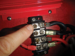
The symptoms of a stuffing box in dire need of service include a series of badly rusted hose clamps and shaft coupling; a shaft log bolt supporting too many bonding wires; and a broken bonding wire.
Start with the prop-shaft nuts. They should be quite tight and the inner nut, if there are two, should butt directly against the prop. If the shaft is drilled to accept a cotter pin, be sure the pin is present, of the correct size and made of stainless steel or bronze. The nuts, if they are not both of the same size, should be installed small or shallow one first, and large or deep one second.
Check the prop blades for dings, chips or dents. Inspect the blade tips for signs of electrolytic action. If this portion of the prop looks corroded, immediate attention is required. It may take hiring a good marine electrician to find and correct the source of this electrolysis or galvanic corrosion. If the prop surface appears uniformly pink, dezincification is at work and essentially your bronze propeller is turning into a useless piece of soft copper. The prop should be replaced, as its structural integrity is questionable. Again, the source of the electrolytic action should be located and stemmed.
If the back surface of the blades appears pitted or unusually rough, then excessive cavitation has occurred. This usually indicates that the prop pitch is too great, causing air bubbles to form on the trailing surface of the blade where they violently implode, taking a little metal with them each time. If only minimal damage has been done, usually this can be corrected by repitching rather than replacing the prop.
Check the blades for proper alignment. You may not be able to do this as accurately as a prop shop can on a bench, but you can get a rough indication of blade position by holding a stationary object, such as a screwdriver, against the strut with a C-clamp. Turn the prop until the tip of the screwdriver has a few thousandths of an inch clearance, perhaps the thickness of two or three sheets of legal pad paper, between it and the blade tip. Now, tighten the clamp and rotate the prop so each blade passes the screwdrivers tip. The clearance should remain constant. If it doesnÕt, the prop should be reconditioned. A misaligned blade will vibrate and could cause premature cutless-bearing failure, among other problems.
Check The Shaft
You can determine the “trueness” of the shaft with a similar test. Normally it is carried out with a dial indicator. This will measure deflection of one-thousandth of an inch. Up to five-thousandths is usually acceptable. The screwdriver will give a rough indication of a larger deflection that would require immediate attention.
In our boatyard we routinely “dial” shafts in three or four locations, even for new shafts. The shaft is first sanded smooth with emery cloth to remove all paint or marine fouling at each dial station. The dial is then set up and monitored by one person while another rotates the shaft through several 360s. Deflection is usually indicated on the shaft with a felt-tipped marker for reference purposes. The stations are usually at the taper (the area aft of the prop likely to show the most deflection if the prop has struck an object), two locations between the strut (if any) and the shaft log, and just aft of the coupling. Performing measurements such as this will give an accurate indication of the shafts “straightness.”
The taper, as well as the key and keyway, should receive attention also. First remove the prop. Props are installed with what is known as an interference fit. Hitting the leading edge of the prop with a hammer or torching it until it glows can damage the prop, and these methods usually dont work. Every blow the prop receives from a hammer is transmitted directly to the bearings and gears of the transmission. Props are designed to be ÒstuckÓ on the shaft. Use a proper prop puller, or have the yard do it. Usually the fee will be nominal.
Once the prop is removed, you can closely inspect the key, a small bronze rectangular bar, and the keyway, its home. This seemingly insignificant piece of metal bears a tremendous burden, transmitting a great deal of torsional energy from prop shaft to prop. Keys come in all different sizes and are usually made of stainless steel or bronze. If the key doesnt fit snugly in the keyway, the prop will shift on the taper, leading to a loose prop or shearing of the key. The result is permanent neutral — no forward and no reverse.
The key should fit with a little interference. Once tapped into the keyway, it should not fall out if the shaft is rotated. The keyway is a weak link in the shaft because some metal must be removed to create it. Cracks can form where the keyway begins (the end farthest from the threads). Look closely at this area because the cracks will be nearly invisible. Any crack is too big; if you discover one, the shaft is destined for the scrap pile. Some shaft manufacturers and prop shops will “spoon” the keyway. This is a soft transition from shaft to keyway at the leading edge. Spooning will help spread the load that the shaft carries in this area.
The threads should be inspected to determine if any damage or evidence of cross threading is present. If any threads show minor dings or dents, these can usually be repaired in the field with the proper die or files, or by a competent machinist/prop shop. If a bronze nut is run repeatedly over a damaged stainless thread, the harder stainless will remove material from the nuts threads each time. This will weaken the nut and eventually render it unfit for service.
Bearing Replacement
The cutless bearing, as its name implies, is the bearer of some load. This is the weight of the shaft and prop, and the torsional loads imparted on it when these are in motion. It is usually constructed with a rubber inner liner that is permanently bonded to a brass outer shell. A word of caution here: If the strut is made of aluminum, a brass-shelled cutless bearing must not be used. Brass and aluminum are galvanically incompatible, and severe damage will be done to the less noble aluminum strut if the two are put in contact. For aluminum struts, fiberglass-shelled bearings must be used; these can be used also in bronze struts. Fiberglass bearings are a welcome sight to a boatyard worker who has been detailed to remove one because they let go much more readily than their brass cousins. The lubrication for a cutless bearing is seawater, which is a fair lubricant but not a great one.
The bearing eventually will wear out and require replacement. The shaft does not necessarily have to be removed to inspect it. Instead, simply grab the shaft just aft of the strut (or stern tube if this is where it is fitted) and give a good shake. If more than just some slight movement is noticeable, replacement is advisable. If the shaft moves enough to cause an audible thunk, replacement is overdue. This bearing is also held captive by virtue of an interference fit, usually supplemented by a few set screws. The bearing should reside tightly in the strut with no spaces or separation visible. If the cutless bearing is of the brass-shelled variety, it too can suffer from electrolysis. This will be evident if the ends of the brass tube appear pink and crumbly. Even a severely corroded bearing usually refuses to fall out or spin; rather, it tends to get quite stuck. It is better to remove it in a familiar location with ample time rather than as a transient in a yard far from home where do-it-yourself labor is prohibited.
Check The Strut
Generally the strut is not considered serviceable, but neglect or failure to inspect it will cause difficulties in the long run. Struts are most often made of bronze, though sometimes as previously mentioned of aluminum or stainless steel. They are usually attached to the vessel by strut bolts and herein lies the weakness. Strut bolts, because of the impossibility of inspection without removal, present some risk of failure. Certainly the strut should be anchored solidly and bedded in place. Movement of the slightest degree is unacceptable. Although some builders use stainless steel bolts to secure struts, presumably for their strength, not for cost savings, I feel that they are too susceptible to crevice corrosion if their bedding fails. I have seen 3/8-inch stainless-steel bolts that were completely parted as a result of extended exposure to oxygen-depleted seawater. Amazingly, these bolts were securing, or failing to secure, lifting eyes in the keel of a 24-foot motorboat. High-quality silicon bronze bolts and a backing plate should be used for applications such as this. If stainless bolts are discovered during an inspection and they are over five years old, then serious consideration should be given to replacement. All of these caveats hold true for shaft logs/stern tubes that utilize stainless hardware.
The shaft should pass through the cutless bearing with perfect alignment so it doesnt pinch the cutless bearing. If pinching is evident, usually then the strut will require a shim between it and the hull. Shims should always be constructed from non-compressible material, such as epoxy thickened with glass fibers, not from elastic bedding compounds or adhesive sealants.
The final area to check at this end of the shaft is the taper. The taper works in unison with the key and keyway actually to transmit energy from the shaft to the prop. The taper on the shaft interfaces with the taper in the prop hub. This creates a locking effect that renders the prop immovable when it comes time to remove it. The taper should be smooth and uniform. Any minor irregularities should be removed with an emery cloth; major ones merit a trip to the prop shop. The prop should not exhibit any lateral movement at all when pushed firmly onto the taper. This must be, as mentioned earlier, an interference fit.
Stuffing Box And Stern Tube
I’ve always thought the stuffing box should be called a stuffing round, because it has very little in common with a box. Nevertheless, it does serve an important role. The stuffing box allows the shaft to pass through the hull and spin, while keeping seawater out. It does this by packing successive sections, usually three, of waxed flax line around the shaft and holding them there under slight pressure with a packing nut. This line, or packing, is able to perform this task by being lubricated, like the cutless, with water. The seawater keeps the packing cool and slippery. If the packing nut is overtightened, it will prevent enough cooling water from reaching the packing within, melting the wax, which then runs out of the packing. This will allow water to pass through the packing and into the boat. If allowed to continue, the packing will disintegrate eventually and the drip will become a run. I am of the “let it drip” school of thought. It is better for a stuffing box to drip too much rather than too little. If it drips too much, it can always be tightened. However, if overtightened, damage occurs rather quickly and a second chance will not be forthcoming. Even though I am an advocate of keeping the bilge as dry as possible to avoid all sorts of other problems, I make an exception here. There are many theories concerning the rate of drip when the shaft is stationary. For the low rpms that a sailing vessel’s auxiliary is likely to turn, one drip every five to eight seconds should be safe. For gasoline-powered vessels running at higher rpms a drip every three seconds would be safer.
There are several configurations of stuffing boxes that use several methods to lock the packing nut in place. This is obviously vital as this nut, if allowed to spin off, will enable a substantial amount of water to enter the vessel. I have seen this result nearly in the loss of a boat. Some systems utilize a locking, or jam, nut that is spun up tight against the packing nut. It is important to use two wrenches when tightening this style of nut. One wrench must be used to hold the packing nut and the other to turn the lock nut against it. If only the locking nut is turned, then insufficient friction will be developed to carry out the locking effect. Other systems, dubiously called self-aligning, use twin studs that run parallel to the shaft with nuts on each affording the clamping action. These nuts are usually doubled and also locked against each other using two wrenches. Still other stuffing boxes employ a cotter pin to lock the packing nut in place. No matter what the system, be sure it is operating properly because the watertight integrity of the vessel will depend on it.
Super Hose
The stuffing box is attached to the stern tube or shaft log with a short section of special thick-wall (five-ply minimum) hose. Ordinary water hose should never be used because it cannot withstand the torsional loads imposed upon it. The hose that is used is closely related, if not identical, to exhaust hose. Because of its thickness, this hose will not compress much. Due to this characteristic, the hose should fit snugly on all components before the clamps are tightened. The clamps in this application are frequently found in poor condition, if not completely broken, due to the amount of seawater that runs over them. It is not uncommon to see all-stainless-steel clamps crevice corroded right through. Because these clamps are usually overtorqued, it doesn’t take a lot of corrosion for them to fail. To avoid this, a solid stainless steel clamp should be used. These clamps differ from ordinary hose clamps in that the threads for the screw do not perforate the clamp band. As a result, they are much stronger and virtually impossible to strip, even when using a socket wrench. Also, due to their thickness, they can live a much longer life in conditions that keep them constantly wet with seawater.
One final word about stuffing boxes. Before attempting service or repairs, determine whether the threads are right or left hand. Some stuffing boxes will make use of a thread that would only tighten the packing nut when the shaft is turning to propel the vessel in forward. This could be beneficial if the locking nut should loosen. Thus, some packing nuts, depending on the direction the prop turns when in forward (clockwise in this case) could require counterclockwise turns for tightening.
The stern tube is the tube through which the shaft passes in order to exit the hull. The forward end of this tube supports the stuffing box and, in some applications, the aft end will support a cutless bearing. The shaft should run directly through the center of this tube without making contact. If the shaft is allowed to chafe against the inside of the stern tube, it will eventually wear through it, allowing seawater to enter the vessel. Many a boat has been lost by this action. I would say that fully 25 percent of the stuffing boxes that I remove reveal a shaft that is wearing a hole in the stern tube. Check for wear by looking closely at the inside wall of the stern tube when the shaft is removed. Areas that look polished indicate that the shaft is coming in contact with something that it shouldnt and further investigation is called for.
The Coupling
The coupling connects the prop shaft to the output flange of the transmission. The mating surface of this coupling is precisely ground and should be perfectly flat so that it will mate to its matched partner, the transmission flange. The prop shaft is usually pressed into the coupling and secured in place with the aid of two set screws. These set screws fit securely into machined dimples, which are drilled 90 degrees apart and must align perfectly with the threaded holes in the coupling. Alternatively, the shaft might have a key and keyway arrangement not unlike the propeller. It would also utilize a nut, and this end of the shaft would be threaded, too. The nut will either be castellated or incorporate a nylon-locking insert. If castellated, be sure a new cotter pin is installed each time the nut is removed. If it is of the nylon-locking style be sure the nylon insert is still substantial enough to provide locking friction. I would not recommend using any nylon nut twice.
If set screws are used, it is imperative that they be safety wired in place. This means the set screws must be drilled to provide a hole for seizing wire to pass through their heads. Be careful; they are made of hardened steel and should not be struck with a center punch. Always wear safety glasses when drilling. The seizing wire should be of a sufficient diameter and strength, preferably stainless steel or monel, to prevent the set screws from vibrating loose. It is also important to twist the wire tightly between the set screws to lock them into place. Using a thread-locking compound affords double security and may actually aid in removal years later. If these screws are allowed to rust in place, they could become impossible to remove. The only alternatives are either to drill them out or to cut the prop shaft Ñ both unpleasant and costly tasks. The coupling and set screws, if not painted (never paint mating surfaces), should be treated as often as necessary with a corrosion inhibitor. It is better to use a type that dries to a waxy consistency rather than the silicone-based products that stay wet and will fly off from centrifugal force.
The bolts that attach the coupling to the output flange should be made of mild steel and meet or exceed grade 5 specifications (at least three hash marks on their head). These bolts should never be replaced with stainless hardware. Stainless bolts of the same diameter are not as strong as high-carbon steel. (Most stainless bolts are only grade 3 or lower rated — two hash marks on the head.) These bolts should be installed with a lock washer, if clearance permits, and a thread-locking compound. If replacing these bolts, be certain that they will not strike any part of the transmission housing. They may need to be cut to provide this clearance.
—————————————————————————
In Part II Steve D’Antonio will explain how to align shaft couplings, what tools are needed to remove and replace cutless bearings, and how to handle stuffing box leaks.