Diaphragm Pump
Think about all the ways a marine-plumbing system moves water and waste through a boat. An impeller pump draws raw water from outside to cool a running engine. A diaphragm pump distributes freshwater, hot or cold, from an onboard storage tank to the galley, head and shower. A piston pump draws seawater into the toilet, then distributes waste for treatment and discharge or to a holding tank from which it will be pumped out later. A centrifugal pump sends bilgewater overboard to prevent sloshing or even sinking.
Understanding marine pumps begins with grasping how liquids behave in an enclosed space. For starters, liquids behave fundamentally differently from, say, the gases in your engine’s cylinders. Gases can be compressed; their density changes when the pressure on them changes. But liquids cannot be compressed. Under pressure, a liquid’s density remains constant. Because liquid doesn’t compress, the only other thing it can do when it’s placed under pressure is to expand. If there’s an open space in the system, the liquid will expand to fill that space, and even spill out from it. When water runs through a pump’s outlet port or out the tap of a galley faucet, it’s doing exactly what it’s designed to do. But in some cases—say, at the overboard vent to a fuel tank—you might see an undesirable, even illegal, result of the same principle. If you overfill the tank, what you’ll see is fuel spilling out through the vent and into the harbor. In either of those cases, desirable and undesirable, the liquid expands till it leaves the system.
Liquids are always under some pressure—ambient pressure—even before they enter such enclosed systems as pumps or hoses. With nothing else acting on it, a cubic foot of water weighs 62.4 pounds. If you divide the base of that cube by 144 square inches, you’d measure 0.433 pounds per square inch. And the more cubes you stack, the greater the pressure at the base of the cube. The pressure at the bottom of 5 cubic feet of water is 2.17 psi; at 10 cubic feet, 4.33 psi. If you’ve ever dived on your anchor, you know firsthand what pressure like that can do. What’s more, air is heavy, too. Stack one-inch cubes of air from sea level to the top of the atmosphere, and it weighs 14.7 pounds at the bottom of the column.
In any plumbing system two ways to change the pressure on a liquid are to change the weight of the liquid itself, or to act on the liquid with a pump. Let’s look at pumps.
There are several basic pump designs you’re likely to find on today’s boats. The first question we ask of a marine pump is whether or not it is “self-priming”—meaning that it can be mounted somewhere above the level of the liquid it’s meant to pump, and it will still draw that liquid when called upon to do so. When speaking of “the level of the liquid,” remember that a boat underway will roll, pitch and heel. Think about the extremes of a boat’s motion underway when you’re thinking about water levels.
Three typical kinds of self-priming pumps are diaphragm pumps, piston pumps, and impeller pumps. A centrifugal pump is not self-priming, and must therefore be installed below the level of water it’s meant to pump.
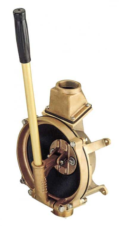
| |A manual diaphragm pump can move a large volume of water and is good to have as a backup bilge pump. This model from Edson can pump up to 18 gallons a minute.|
Diaphragm Pumps
Diaphragm pumps (along with piston pumps and impeller pumps) are among the family of “positive-displacement” or “variable-volume” pumps. All the pumps in this family work by changing the volume inside the pump chamber. In diaphragm and piston pumps, check valves at the pump’s inlet and outlet ports regulate where the water comes in from and where it flows out to. Diaphragm pumps are named for the flexible rubber diaphragm that stretches across one side of the pump housing. In fact, you have a muscle that stretches across your chest called a diaphragm. Your lungs are a kind of diaphragm pump. When your diaphragm contracts, it increases the volume of your chest cavity; vacuum pressure draws air into your lungs.
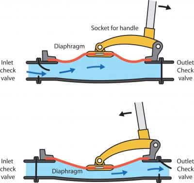
With mechanical diaphragm pumps, pushing a handle back and forth moves the diaphragm up and down, expanding and contracting the space inside the housing. When the space expands, it creates vacuum pressure at the inlet port, drawing water in. The check valve on that end is designed to open in that direction but close when the hydraulic pressure comes from the other direction. When the pump handle moves down, it contracts the volume inside the chamber, forcing water out past the outlet valve.
Diaphragm pumps share several drawbacks with the other positive-displacement pumps, all of which can be solved. For one thing, they absolutely depend on their check valves in order to work. If any debris or abrasion prevents the valves from seating properly, liquid will just slosh back and forth past the housing instead of flowing purposefully through the outlet port and into the rest of the system.
Also, as the volume of the housing expands and contracts, the liquid pulses from the outlet port of a diaphragm pump. In some cases, like domestic water service, it can be annoying to have water spurting out from the taps instead of flowing evenly, as it does in our homes. A solution here is to install an accumulator tank, which provides even pressure at the tap.
| |_ Diaphragm Pump _|
Another drawback of positive-displacement pumps is that they provide no inherent relief against excessive pressure. If the outlet side gets blocked, for example, positive-displacement pumps continue to generate output pressure till the handle no longer moves — or until something breaks. Installing a pressure-relief valve solves this problem.
Some diaphragm pumps are operated manually, either with a handle or a foot pump; others are driven by motors. In either case, the pump translates mechanical work into hydraulic pressure inside the plumbing system.
Diaphragm pumps are simple designs, and therefore simple to maintain. If you make sure the rubber diaphragm is in good shape, that the seal around the housing is intact, and that the check-valves are sound and unclogged, the pump should give plenty of dependable service. As we’ll see, there are other pump designs that move water faster. But for simplicity and dependability, diaphragm pumps are hard to beat.
Typical uses for manual diaphragm pumps include backup bilge pumps, while motor-driven diaphragm pumps often supply the domestic freshwater system. If the system is automatically pressurized, it will include a pressure switch. In a typical domestic water installation, the switch might turn the pump on at about 25 pounds per square inch, and off between 35 psi and 40 psi.
|
Piston Pumps
Piston pumps are closely related in design to diaphragm pumps. They too function by changing the volume inside a chamber, and they too rely on check valves to let water enter and escape the chamber when it should. The housing of a piston pump is typically a long cylinder, with inlet and outlet ports.
Again, maintenance with these pumps is fairly simple. One difference, though, is that piston pumps include a shaft that enters the housing to drive the piston. Watch the shaft inlet for leaks. Inside the housing, look for a good seal around the edges of the piston. Make sure the check valves are in good condition and clear of debris. You can expect to find a piston design in some handheld bilge pumps and some manual-flushing heads.
Impeller pumps
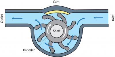
A third type of self-priming pump is an impeller pump. Like the two previous designs, this one works by changing the volume inside the housing. But an impeller pump does not rely on check valves. The impeller is a wheel with flexible blades, usually made of neoprene or some other flexible material that resists abrasion. The impeller turns around a central shaft. But the housing around the impeller isn’t a perfect circle. A cam mounted inside the housing causes each blade to bend, or flex, as it passes over the cam. When the blade flexes, it decreases the volume of the space between it and the following blade. The outlet port is oriented in such a way that it collects the liquid that’s displaced when the blade flexes. On the inlet side, the blade straightens after having passed over the cam. That straightening increases the volume of space between the straightening blade and the following blade, creating a vacuum. The vacuum draws in either air or liquid and delivers it out the outlet port. And so the cycle repeats.
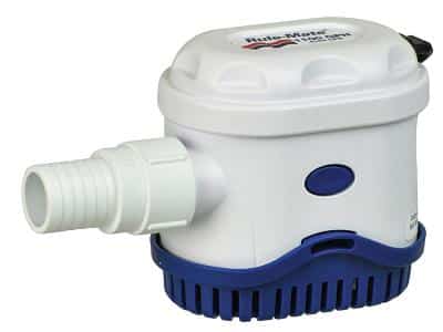
| |_Frequently found in engine cooling systems, impeller pumps cannot operate dry for very long. _|
Impeller pumps have two drawbacks. Because they function by the bending of those small blades, they can’t pass solids. And, although they’re excellent self-priming pumps, impeller pumps can’t run dry for very long at all before the flexible blades get destroyed. Impellers are lubricated by the very water they pump. In some cases, a minute is too long.
An engine’s cooling system is a typical application for impeller pumps. The running engine drives the impeller shaft. We won’t go into too much detail here about engine cooling systems. Just know that if you find yourself troubleshooting an engine cooling problem, and you open the pump housing to find that any impeller blades have broken off and are missing (this happens more frequently than you’d guess), make sure you track down all the bits of material that broke away. If you don’t, they’re very likely lodged downstream in the cooling system, blocking the flow of cooling water. They’ll go on causing problems until they’ve been removed.
When servicing impeller pumps, or any other kind of pump for that matter, take care with all the parts. For example, to get inside the housing of an impeller, you first need to remove the cover plate. Depending on its condition, you shouldn’t be surprised to find that it resists removal. But don’t go prying at it with the steel blade of a screwdriver; instead, give it a couple of taps with a rubber mallet, or try a plastic putty knife. The housing and cover are probably made of bronze, which is softer than a hardened-steel screwdriver. Also, replace any gaskets that seal the cover to the housing. Remember that the parts you’re working with will need to reliably seal liquid after you’ve reassembled them. Scratched or dented surfaces will never seal properly.
Impellers should be replaced annually, or if there’s any sign of wear. In addition to that regular replacement schedule, watch the cam, the cover, and the inner housing for wear.
| |Centrifugal pumps are typically used as a boat’s automatic bilge pump since they’re reliable and only require periodic cleaning.|
Centrifugal pumps
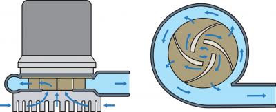
We now turn our attention to a pump design that works differently from those we’ve discussed till now. A centrifugal pump does not displace volume, as a diaphragm or a piston or an impeller does. Instead, its blades spin swiftly, throwing liquid outward from the center of the housing. This is the only pump discussed in this chapter that is not self-priming. For that reason, it will only function if it’s installed below the level of the liquid it’s meant to pump.
The word centrifugal means “away from the center.” You’ve experienced centrifugal force if you’ve ever dangled a yoyo, then spun your body round in circles, faster and faster, with your feet planted. The force away from the center (you) is what holds the yoyo up and out. Or, if you’ve ridden a fast merry-go-round at the playground, the object the centrifugal force was trying to push away from the center was, well, you. If you remember that feeling, you know how forceful centrifugal force can be.
That’s what the spinning blades of a centrifugal pump do to a liquid. They sling it outward. And you can probably guess what happens near the center of a system where liquid is being slung outward. The pressure of the liquid at the center of that system decreases. Here again, we’ve created a vacuum.
We said earlier that one of the big drawbacks of an impeller pump was that running it dry would damage the impeller. And even if the pump never did run dry, the impeller would still need to be replaced annually. Think about it. Those impeller blades hit the cam—bend, straighten, bend, straighten—tens of thousands of times every season.
Centrifugal pumps, by contrast, do not suffer from either of these drawbacks. Their blades never touch the housing, so they never need to be serviced or replaced under normal conditions. Maintenance should include a look at the shaft seals; contact with fuel or oil can sometimes degrade them. Quite often, just cleaning out the strainer is the extent of servicing you can do for a submersible centrifugal pump. The best thing about centrifugal pumps is the high volume of liquid they can pump, hour after hour after hour. For this reason, they’re used quite often as primary bilge pumps. (Some experts recommend a high-capacity diaphragm pump, though, because it is self-priming.)
Repairing Clogged Heads
| |Double-Acting Piston Pump|
An unfortunate fact of life aboard is that marine toilets sometimes clog. For that reason, it’s important that you understand the basic design of the marine toilet. We’ll describe one common design here, but for details on particular toilets you may need to consult the manufacturer’s service manuals.
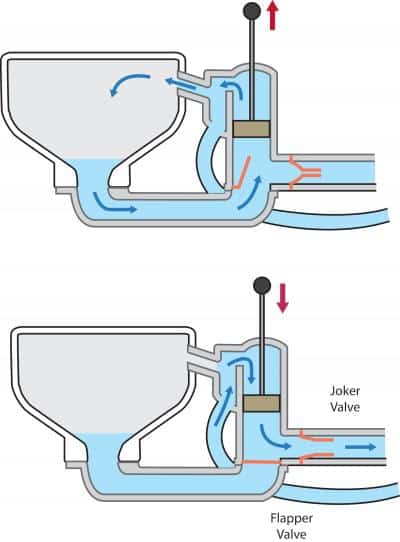
To see a cutaway view of how a common design works, look at illustration above. This is a marine toilet that’s based on a typical double-acting piston pump. A piston pump works by changing the volume inside a housing. Meanwhile, check-valves regulate where liquid flows in and where it flows out. Well, the double-action piston pump works the same way, but with an important difference: the piston is working on both sides of the housing at once.
Here’s how it works. The piston, seated snugly in the pump cylinder, keeps clean flushing water separate from waste. With the intake lever open in the “flush” position, one upstroke simultaneously does two things: It forces clean water from the upper section of the pump cylinder into the toilet bowl, and it draws waste from the bowl into the lower section of the pump cylinder. A downstroke simultaneously draws clean water from the through-hull fitting into the pump cylinder’s upper section, and forces waste out of the cylinder’s lower section into the holding tank.
What keeps all the fluids flowing where they’re supposed to? A series of one-way flexible valves. These are the components that clog and need periodic care and replacement.
Vacuum pressure from the head’s pump draws water through the seacock, the intake hose, and a vented loop on its way to the pump. From here, water is regulated by a rubber check valve, controlled by the “flush/dry bowl” lever on the pump body. Once water enters the pump cylinder (provided the lever is switched to “flush”), it is diverted to the bowl.
Continuing downstream, waste exits the bottom of the bowl and is drawn through a one-way valve, called the “flapper” valve, and into the lower section of the pump body. Vacuum pressure in the pump body during an upstroke lifts this normally closed valve off its seat. As the piston moves down, pressure forces the flapper valve closed, preventing sewage from returning to the toilet bowl. Instead, it exits the pump through yet another one-way valve. This one is called the “joker” valve, because it resembles the classic headgear of a court jester.
The joker valve serves two purposes. First, as a check valve, on the upstroke it prevents water and waste from being drawn back through the discharge hose into the pump body. Second, it begins to break up solid waste forced through the valve’s tight opening. It is common for blockage to occur at this point in the head system.
The failure of any one of these valves means the failure of the head. They will likely become unseated if anything except human waste and a minimum amount of short-fiber toilet paper passes through them. To repair a clogged head, you’ll need to disassemble the parts of the housing that give access to each of those valves, especially on the discharge side. The joker valve and the flapper valve are the two most common culprits for clogs.