step1.jpg
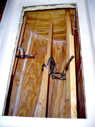
I started by drilling a few .75-inch holes through the top, bottom, and sides of the icebox so I could extract and examine a core sample for each hole. I needed to see the details of what kind of insulation had been used and if the spaces between the box, the hull, and adjacent bulkheads had been filled with foam. To measure those spaces (which were completely empty voids), I simply inserted a small dowel until it made contact with the hull or solid structure. I discovered that my icebox had been made by lowering a laminated interior box liner into the outer molded fiberglass retainer, making a box within a box. The space between the two boxes, a mere 1 inch, was filled with closed-cell urethane foam. The boxes provided zero insulation, and the foam wasn’t much better. Bruce Bingham

step2.jpg
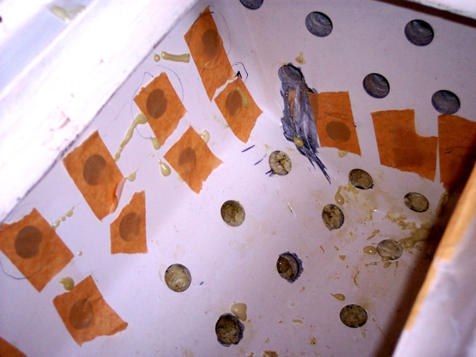
My plan was to pour or inject two-part, closed-cell urethane foam between the molded icebox and the hull, but the foam would have to be confined to prevent it from expanding into storage lockers and other spaces. So I installed a .25-inch plywood bulkhead to separate the “foam space” from the compartment shared by a seacock and frying pans. I drilled additional .75-inch holes about 3 inches apart through the icebox walls, bottom, and counter top. I purchased a single two-part urethane-foam kit that contained just enough to fill the empty spaces around and under the box. Parts A and B were mixed in equal quantities, so I marked a stack of paper cups in advance to the half-full level for easy and accurate mixing. The liquid mixture was injected under low pressure through each hole to reduce time because the foam begins to grow as soon as the mix is stirred. I injected the mixture because I knew that I wouldn’t be able to pour it horizontally through the holes in the side of the box. Plus, injection is faster than pouring. I had just 30 seconds to get the foaming fluid through the hole and into the void to be filled, so I came up with a method that worked like a charm. Bruce Bingham

step3.jpg
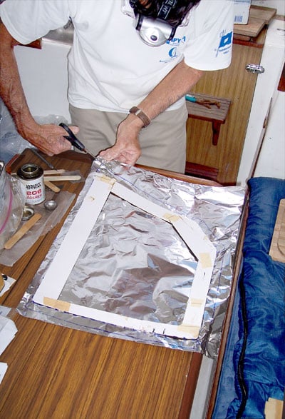
A full paper-cup mixture fit into a resealable plastic bag with room to spare, so first I cut off a small corner of each bag in advance. Then I inserted a 2-inch length of large-diameter drinking straw (from McDonald’s) into each hole and taped them in place with 3M Scotch Magic tape. Basically, I made dozens of miniature cake-icing decorating bags and set them aside. Bruce Bingham
step4.jpg
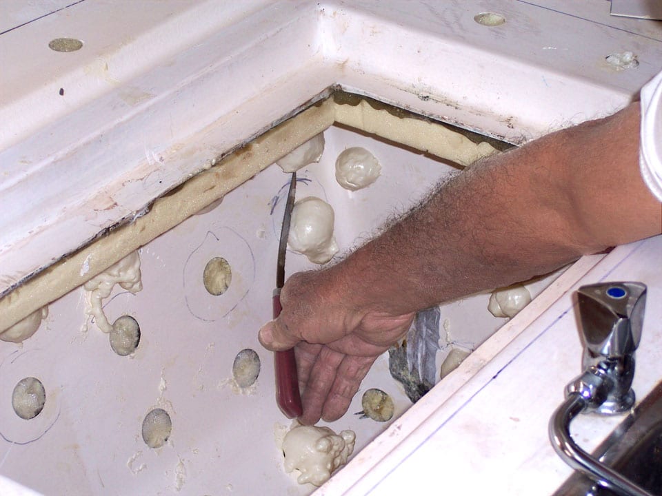
I began at the bottom of the icebox and worked upward. After expending the resealable bag’s contents into a hole, I quickly placed a piece of 2-inch masking tape over it and let the foam go to work. I then mixed the next batch of foam, poured it into another baggie, and squeezed it into another hole, but not one directly adjacent to the previously injected hole, as it took 30 minutes to cure before contacting fresh foam. So I kept the injections some distance apart. For most of the day I continued mixing, pouring the fluid into plastic bags, and injecting mixtures through the bottom, then the sides, and finally into the holes in the counter top. Bruce Bingham
step5.jpg
Each injection was always followed by a clean-up period. This was messy. I used lacquer thinner on my hands, the injection areas, and where I’d left drips. I didn’t stop injecting foam until enough pressure pushed the tape off each hole, signaling that most, if not all voids had been filled. I gave the foam “muffins”—the protrusions from the injection holes—several days to fully cure before shearing them flush with a large knife.

step6.jpg
The original icebox interior was small as well as inefficient, which meant that most of its volume was dedicated to ice rather than to food. It seemed logical to increase the insulation and bolster the efficiency so the contents would last longer without adding more ice. I chose Dow’s Tuff-R polyisocyanurate plank foam (used on NASA’s space shuttles!) with aluminum radiant-barrier sheeting on one side; it has an R factor of 6.5 per inch of thickness. Bruce Bingham
step6b.jpg

step6c.jpg
step7.jpg
As the Tuff-R foam plank has a compression strength of only 25 p.s.i. (which means it can be easily dented), and the aluminum foil would be vulnerable to cans and other objects, I installed a liner fashioned from .25-inch aircraft plywood, each pre-fit panel of which received a layer of 8-ounce fiberglass cloth to harden the plywood and add another moisture barrier. Each panel was carefully patterned before cutting, trimmed for a perfect fit, and completely coated with a brushable epoxy. Before installation, the panel’s exposed sides were covered with a layer of VG (vertical grade) Formica. Again, 3M 5200 was the adhesive of choice. I wanted each panel to fit tightly, so I came up with a temporary bracing system using short lengths of wood and C-clamps pressed into position. I left the braces for each panel in position for a full day before removing them. Given the number of panels, I needed a full week for this operation. I then added a layer of Formica, fastened with 5200; the corner joints received a fillet of white Marine-Tex after careful masking for neatness. Bruce Bingham

step7b.jpg
Finally, I drizzled another small batch of epoxy around the pipe from the interior and allowed it to run into possible voids. The vapor-lock loop was fabricated of copper tubing and elbows that were sweat-soldered for rigidity and water tightness. The loop was connected to the drainpipe with a short section of hose so it can be easily reached and removed for occasional cleaning. This fitting prevents cold air from escaping through the drainpipe. Bruce Bingham

step8.jpg
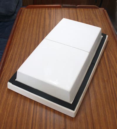
The original box lids had been built of teak with 1-inch slabs of urethane foam. Since teak provides no insulation and would’ve clashed visually with the new white Formica counter top I also installed, I started from scratch and fabricated a brand-new two-sectioned hinged lid. The majority of the lid was made of three layers of 1-inch Tuff-R foam with the aluminum radiant barrier removed. A paste epoxy was the laminating adhesive. Once the epoxy had kicked off, the edge shaping was done on my table saw to “almost perfectly” fit the icebox opening. I had to leave adequate tolerance for the addition of four layers (mat, cloth, mat, cloth) of fiberglass. Before glassing, though, the top and bottom surfaces of the lid received a layer of .25-inch aircraft plywood adhered with paste epoxy. Bruce Bingham
step8b.jpg

step9.jpg
The original icebox had no system for separating its contents with dividers or a tray, which meant that the lid would be open for long periods while one rummaged around for coleslaw or hot dogs. So I made transverse and longitudinal .25-inch dividers out of clear polycarbonate plastic, again starting with accurate patterns taken from the icebox interior. Each divider was fashioned with heat-bent flanges to receive small stainless-steel sheet-metal screws or machine screws with nuts. Where the sheet-metal screws penetrated the icebox walls, I used 3M 5200 as a sealant to prevent water from seeping into the foam structure. The transverse divider was located to accommodate the eventual installation of a refrigerator evaporator. I also made a small, high-sided, removable tray from the polycarb. The void under the tray was accessible and usable for food storage. Limber holes in the tray and dividers were added for drainage. Finally, a small piece of plastic screen was crumpled up and pushed into the drain to prevent food from becoming lodged in the pipe or vapor loop. Wrapping Up:
Once the project was finished, the melt rate of cubed ice was reduced to about 3.5 ounces per hour. When I cruise for long distances, I use block ice sculptured to fit the box shape fairly snugly, and I fill the voids with ice chips and cubes. Then the melt rate drops to about 2.8 ounces per hour. About two years after the rebuild, I added a small refrigeration system, which was expensive but easily installed. I located the condenser in the starboard cockpit locker, with plenty of ventilation, and the evaporator slipped into the allocated icebox compartment perfectly. Improving the icebox vastly extended my cruising range and virtually eliminated the daily trips for ice even before I installed the fridge. The time and temporary mess were worth it. What a difference! What a joy!