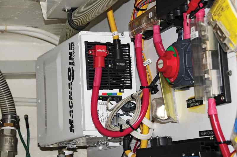
Vertically Mounted Inverter
Over the last two decades, inverters have become one of the most popular pieces of equipment on cruising boats. In fact, new boats that don’t carry inverters are now the exception. Even so, for many sailors, their inner workings remain a mystery. More importantly, few cruisers fully understand the specifics and hazards of installing them.
Inverters electronically convert the power from 12- or 24-volt DC batteries to 120- or 240-volt AC current (the same as shore power or household electricity, albeit with lower capacity). Most inverters are also capable of reverse operation to create battery voltage from the power derived from either a shore-power connection or a generator. In other words, they’re battery chargers too, and often very effective ones.
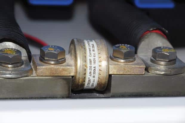
| |Most inverters require “class T” fuses, like the one employed here.|
Because of the loads involved, the supply cables for inverters are big (depending upon the unit’s output and the cable length, they can be thumb-size or larger). So the positive cable must be protected by a fuse, which in turn must be installed close to the power source, either the battery bank or positive bus. ABYC guidelines dictate that the distance between the fuse and battery be no more than 7 inches (however, if the cable is supplementally sheathed, or housed within a conduit, it may be as long as 72 inches).
Additionally, most inverter manufacturers employ a specific type of “class T” fuse, rather than the more common and less expensive ANL-series fuses. The difference between them is in their “arc interrupt capacity,” a matter that becomes more important as battery-bank capacity increases. In addition to a fuse, for both servicing the inverter and disabling it in the event of a fire or malfunction, an inverter’s DC supply cabling should also be equipped with a disconnect switch.
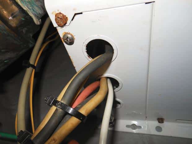
| |With no strain relief or chafe protection, this wiring is a safety hazard.|
Most inverter manufacturers are very clear about how and where to install their products. This is partially a fire-prevention issue; internal components can sometimes “spill” from an inverter’s heated louvered surfaces onto a wood or composite shelf. For this reason, several suppliers prohibit inverters from being installed on horizontal surfaces. And inverters should never be installed directly above battery banks.
To reduce the likelihood of electrocution, the inverter chassis must be bonded or grounded. While that’s also typical of most shore-powered appliances, the inverter is different. Because it’s also connected to the DC system with those aforementioned large cables, the ground wire must be capable of conveying fault current from either the AC or DC system. Therefore, the inverter’s chassis ground must be the same size as the DC system’s positive cable, a fact that surprises even many boatbuilders and professional installers.
The final issue in many inverter installations is the manner in which the AC cables pass through the inverter’s metallic case. Rather than simply passing through a sharp metal hole, these wires should always rely on strain-relief connectors or cord grips. The latter serve two important purposes. First, they prevent the connections within the inverter from being stressed if the cable is pulled or tugged (I saw this happen when a boat hook became entangled with the wire and the owner’s teenage grandson simply heaved harder, yanking the energized cables out of the inverter). Second, they prevent the cables from chafing against the case, again leading to possible electrocution.


